
Introduction
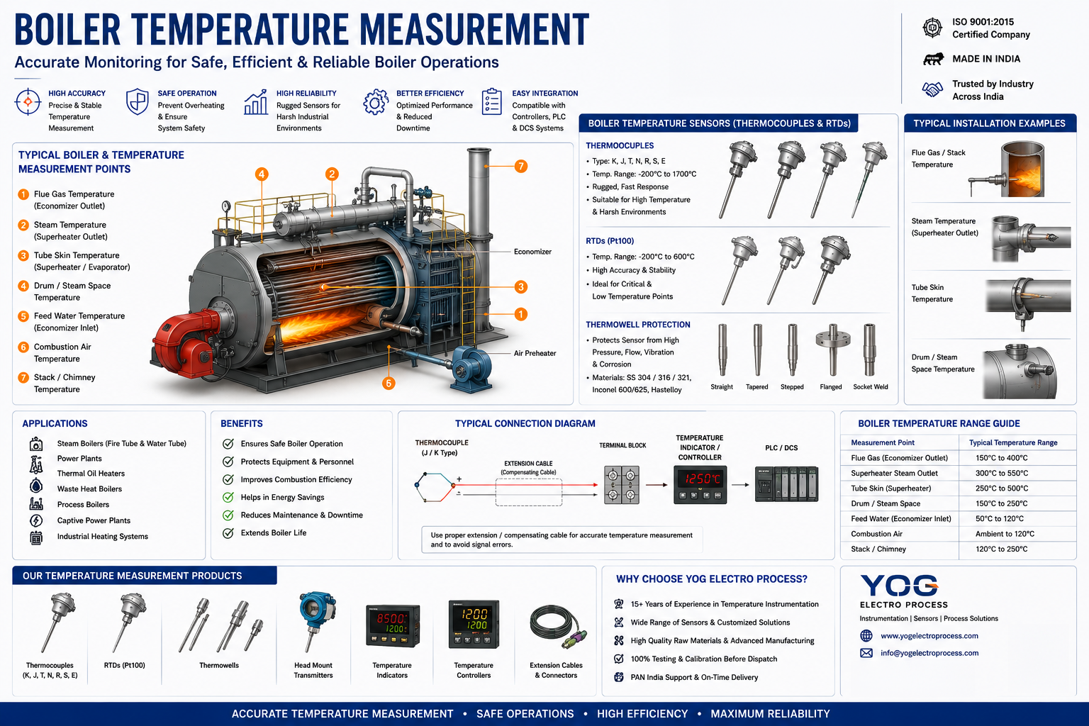
Boiler temperature measurement supports combustion control, heat-transfer monitoring, steam-condition verification and equipment protection. Each point has different temperature, pressure, flow and response requirements.
A flue-gas sensor cannot be specified like a feedwater RTD, and a steam thermowell must be reviewed for process loads rather than selected by connection size alone.
Process Context
Furnace and flue-gas points encounter radiant heat, ash, corrosive products and changing gas velocity. Steam and water points add pressure and thermowell stresses. Bearings and auxiliary equipment operate at lower temperatures but may require faster detection of abnormal rise.
Useful boiler monitoring combines process measurements with equipment-condition measurements. The control philosophy determines whether speed, long-term stability, replaceability or pressure containment has priority.
Selection Guidance
Use thermocouples for hotter combustion and gas-path points. Use Pt100 RTDs where tighter accuracy is required at moderate temperatures, such as feedwater, condensate or bearings.
For pressurized piping, specify the sensor and thermowell as a system. Confirm material, insertion length, process connection, velocity, pressure, vibration and response requirement before finalizing the design.
Recommended Sensors
Type K or N thermocouple
Furnace, uptake and flue-gas duties within the selected sheath or protection tube's limits.
Pt100 RTD assembly
Feedwater, condensate, bearings and auxiliary systems requiring stable moderate-temperature measurement.
Replaceable insert with thermowell
Pressurized steam or water lines where the sensor must be removable without opening the process.
Installation Considerations
Locate gas-path sensors where they represent the intended flow and are accessible for inspection. Avoid wall effects, direct flame impingement and ash accumulation unless the point is designed for them.
Thermowells in steam or high-velocity flow require mechanical review. Sensor insertion should reach the active tip of the well, with spring loading where needed to maintain thermal contact.
Key Benefits
- Separates combustion, heat-transfer and equipment-protection measurements.
- Improves control decisions by matching response to each measurement point.
- Supports safe sensor replacement on pressurized lines.
- Reduces failures caused by ash, corrosion, vibration or poor thermowell fit.
Specifications
| Measurement duty | Typical approach |
|---|---|
| Furnace / flue gas | Type K or N with heat- and corrosion-resistant protection |
| Steam line | Thermocouple or RTD insert in an engineered thermowell |
| Feedwater / condensate | Pt100 RTD with suitable process connection |
| Bearing temperature | Compact RTD or embedded/surface sensor |
| Indicative overall range | -50°C to 1200°C, point-dependent |
Frequently Asked Questions
Which sensor is used for boiler flue gas?
Type K or N thermocouples are common, but the sheath or protection tube must match gas temperature, ash loading and corrosion conditions.
Is an RTD suitable for steam temperature?
An RTD can be suitable within its range and mechanical design limits. The thermowell, pressure rating and required response must also be evaluated.
Why is a thermowell slow to respond?
Heavy wall thickness, excessive air gap, poor insert contact and large tip mass increase lag. Faster response must be balanced against mechanical strength.
Where should boiler bearing temperature be measured?
The point should provide repeatable thermal contact close to the bearing condition being monitored without interfering with lubrication or maintenance.
References
Need an engineered solution?
Speak with our technical specialists to design a sensor assembly perfectly matched to your application requirements.
Contact Engineering Team