
Introduction
A rotary hearth furnace moves work through a circular sequence of heating zones. Control quality depends on understanding both zone temperature and the thermal history created by hearth speed, burner balance and load arrangement.
Thermocouples must represent each controlled zone without being exposed to charge impact, excessive radiant bias or vibration from the furnace structure.
Process Context
Load density and hearth rotation continually change local heat absorption. Door openings, seals, burner condition and exhaust flow can create differences between indicated zone temperature and the temperature experienced by the work.
Fixed control sensors support zone regulation, while surveys or load-mounted sensors may be used separately when actual workload history must be evaluated.
Selection Guidance
Type K or N suits many furnace-control duties. Type R or S may be selected where temperature and stability requirements exceed base-metal capability. Protection must withstand scale, radiant heat and cycling.
Choose response time according to control needs. A very heavy protection tube lasts longer but may hide short zone changes; a lighter assembly responds faster but may require more frequent replacement.
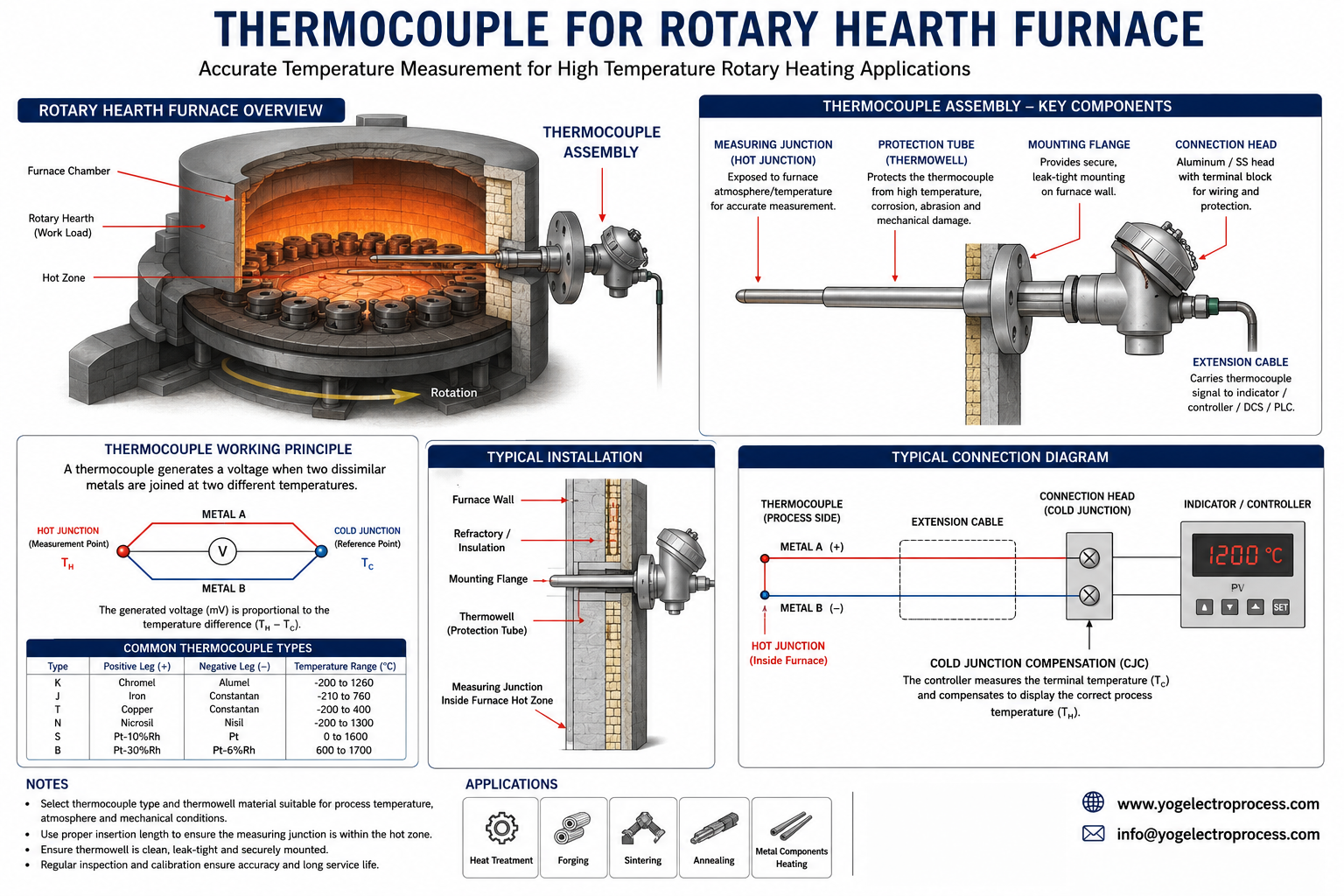
Recommended Sensors
Type K or N zone thermocouple
General zone-control measurement with protection selected for furnace atmosphere and temperature.
Type R or S ceramic assembly
Higher-temperature zones requiring noble-metal thermoelements and ceramic insulation.
Survey thermocouple
Temporary or workload-mounted sensing used to evaluate the thermal profile separately from control.
Installation Considerations
Use consistent insertion and orientation across comparable zones. Protect the probe from moving work and allow sufficient clearance for hearth runout, loading equipment and maintenance access.
Inspect support brackets, entry seals and cable routes for vibration damage. Compare sensor trends with burner condition and hearth loading before treating every deviation as sensor failure.
Key Benefits
- Supports balanced control across multiple heating zones.
- Clarifies the difference between zone indication and workload history.
- Reduces mechanical damage from moving loads and vibration.
- Improves troubleshooting by linking sensor trends with hearth operation.
Specifications
| Design item | Typical options |
|---|---|
| Measurement purpose | Zone control, over-temperature protection and thermal survey |
| Thermocouple types | K, N, R or S |
| Indicative range | Ambient to 1400°C, assembly-dependent |
| Protection | Heat-resistant alloy or ceramic protection tube |
| Critical variables | Hearth speed, load pattern, burner balance, insertion and response |
Frequently Asked Questions
How many thermocouples does a rotary hearth furnace need?
The number depends on furnace zoning, burner arrangement, size, control philosophy and required over-temperature protection. Each controlled zone normally needs representative sensing.
Does the control thermocouple show workpiece temperature?
Not directly. It measures its local furnace environment. Workpiece temperature also depends on residence time, section size, load pattern and heat transfer.
Why do adjacent zones read differently?
Differences can come from burner balance, exhaust flow, door leakage, load density, sensor insertion or an aging sensor. Process and sensor checks should be performed together.
Should the fastest thermocouple always be selected?
No. Response must be balanced against mechanical strength, protection and expected service life.
References
Need an engineered solution?
Speak with our technical specialists to design a sensor assembly perfectly matched to your application requirements.
Contact Engineering Team