
Introduction
Blast-furnace temperature measurement combines very different duties. Shell and cooling-system points track equipment condition, refractory points indicate heat migration, and hot-blast or gas measurements support combustion and energy control.
A thermocouple assembly must be designed for its exact zone. Choosing only by maximum temperature can produce a sensor that survives the heat but fails from abrasion, vibration, reducing atmosphere or mechanical loading.
Process Context
Hot-blast stoves and mains experience elevated temperature and repeated cycling. Furnace shell and refractory monitoring require repeatable positioning so trends can be compared over time. Top-gas and duct measurements add flow, dust and access constraints.
The useful signal is often a trend rather than one isolated value. Stable installation depth, consistent junction location and reliable cable routing are therefore essential when readings are used to assess refractory condition or cooling performance.
Selection Guidance
Define the furnace zone, normal and upset temperature, gas composition, solids loading and expected replacement method. Select the thermoelement, then specify sheath or protection tube, insertion length, process connection and connection head.
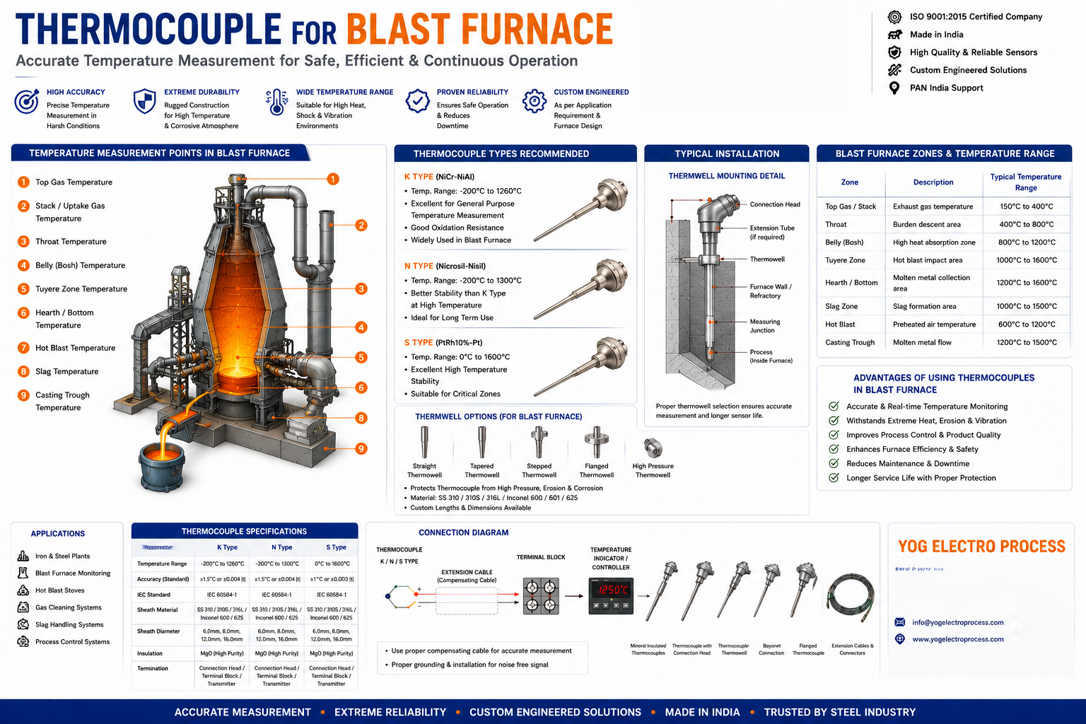
Type N can provide improved high-temperature stability over Type K in some long-duration duties. Noble-metal types may be considered for the hottest zones, but only with appropriate ceramic insulation and protection.
Recommended Sensors
Mineral-insulated Type K or N
A rugged choice for shell, duct and hot-blast points within the alloy sheath's temperature and atmosphere limits.
Type R, S or B with ceramic protection
For selected very-high-temperature locations where noble-metal stability is required.
Surface or embedded thermocouple
For shell and refractory trending where repeatable contact and protected routing are critical.
Installation Considerations
Prevent unsupported insertion lengths from vibrating in high-velocity gas. Use a suitable support or thermowell and confirm that wake, pressure and mechanical loads are acceptable for the assembly.
For shell or refractory trending, preserve the same depth and contact condition when replacing a sensor. Protect extension cable from hot surfaces and document polarity, junction type and terminal location.
Key Benefits
- Provides dependable data for combustion and hot-blast control.
- Supports refractory and shell-condition trending.
- Reduces repeat failures by matching protection to dust, heat and atmosphere.
- Improves replacement consistency through defined insertion and mounting details.
Specifications
| Design item | Typical options |
|---|---|
| Measurement zones | Shell, refractory, hot-blast main, stove, top gas and auxiliary systems |
| Thermocouple types | K, N, R, S or B according to zone and range |
| Indicative range | Ambient to 1700°C, assembly-dependent |
| Protection | Inconel/heat-resistant alloy sheath, ceramic or silicon-carbide tube |
| Mounting | Threaded, flanged, welded pad, embedded or thermowell assembly |
Frequently Asked Questions
Which thermocouple type is used in a blast furnace?
Type K and N are common for many plant points. Type R, S or B may be selected for higher-temperature zones. The final choice depends on atmosphere, protection system and required service life.
Is a ceramic tube always required?
No. Ceramic protection is useful at high temperatures and in specific atmospheres, but a metal-sheathed mineral-insulated sensor may be better for vibration, response or compact installation.
How is refractory temperature monitored?
Plants use embedded or strategically positioned thermocouples to trend heat movement through the lining. Repeatable depth and location are essential for meaningful comparison.
Why does a hot-blast thermocouple drift?
Drift can result from thermoelement aging, contamination, insulation breakdown, thermal cycling or changes in insertion and heat transfer.
References
Need an engineered solution?
Speak with our technical specialists to design a sensor assembly perfectly matched to your application requirements.
Contact Engineering Team